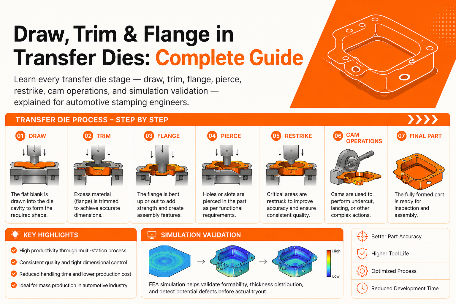
A transfer die does not create a component in one operation. It forms the part progressively through multiple engineered stages — draw, pierce, trim, flange, restrike, and cam operations — until the final automotive stamping meets dimensional and production requirements.
Every station in a transfer die sequence has a specific purpose. Incorrect sequencing can lead to splits, wrinkles, springback issues, dimensional inaccuracies, and expensive tryout corrections.
For automotive OEMs and Tier-1 suppliers, understanding transfer die stages is essential for:
- Process planning
- Tooling validation
- Cost optimisation
- AHSS forming feasibility
- SOP risk reduction
At Dai-Ichi Tools, transfer dies are engineered using AutoForm R12 simulation, in-house tryout validation, and precision machining for automotive structural and body panel applications.
This guide explains every major transfer die stage, how each operation works, common failure modes, and how simulation validates the complete forming process before production begins.
Key Takeaways
- Transfer dies form parts through multiple sequential stations
- The draw stage controls overall part geometry and material flow
- Trim and flange sequencing directly affect dimensional accuracy
- Restrike stations help correct springback in AHSS components
- AutoForm simulation reduces tryout corrections and SOP delays
- Proper station sequencing improves part quality and material utilisation
How a Transfer Die Builds a Part
Every transfer die programme begins with the finished component geometry and works backwards to determine:
- Required forming operations
- Correct station sequence
- Material flow requirements
- Press load distribution
- Blank positioning at every stage
The sequence is critical. A flange formed too early may crack. Piercing before forming may distort hole geometry. Incorrect trim timing can affect downstream flange quality.
This is why transfer die development relies heavily on simulation before manufacturing begins.
Stage 1 — Blank Development & Optimisation
Blank development is the foundation of every transfer die programme. The blank is the pre-cut sheet metal shape that enters the first station.
Blank geometry directly affects:
- Material flow during drawing
- Edge cracking risk
- Material utilisation
- Transfer stability between stations
Why Blank Optimisation Matters
AutoForm simulation helps determine the minimum blank size required to produce a defect-free part.
Optimised blanks help:
- Reduce material waste
- Improve forming stability
- Lower production cost
- Reduce wrinkling and splits
In high-volume AHSS programmes, blank optimisation can generate significant annual material savings.
Blank Edge Quality
For AHSS and UHSS applications, blank edge quality is critical. Poor edge quality increases the risk of:
- Stretch flange cracking
- Edge fractures
- Forming instability
Laser-cut and fine-blanked edges improve flange formability significantly compared to conventional sheared edges.
Stage 2 — Draw Operation (Deep Draw/Form Draw)
The draw station is the most important stage in most transfer die programmes because it establishes the primary three-dimensional geometry of the part. Any dimensional issue introduced during drawing affects all downstream operations.
What Happens at the Draw Station
The blank is clamped by the binder ring while the draw punch forces the material into the die cavity. Controlled material flow is essential:
- Too little binder pressure causes wrinkles
- Too much pressure causes splitting
Main Draw Die Components
Draw Punch: Forms the primary geometry and controls material stretching.
Draw Die: Receives the punch and determines final cavity shape.
Binder Ring: Controls blank holding pressure during forming.
Draw Beads: Restrict local material flow to prevent wrinkling.
Solution: Increase radius and optimise binder force
Solution: Increase pressure or modify draw beads
Solution: Revise blank geometry
Solution: Apply simulation-based compensation
Solution: Improve coating and lubrication
Springback in Draw Operations
Springback is one of the biggest challenges in AHSS transfer dies. For 980 MPa AHSS:
- Angular springback can reach 5–15°
- Surface deviation may exceed several millimetres
At Dai-Ichi Tools, AutoForm springback compensation is applied before machining begins, reducing tryout corrections significantly.
Stage 3 — Redraw Operation
A redraw station is used when the required geometry cannot be safely achieved in a single draw operation. The part is partially formed in the first draw station and then progressively deepened in a redraw station.
Redraw Operations Are Common For:
- Deep box sections
- Cylindrical parts
- Aluminium components
- AHSS applications
AutoForm simulation determines whether a redraw station is necessary before die manufacturing begins.
Stage 4 — Pierce Operation
Pierce stations create:
- Holes
- Slots
- Cut-outs
Piercing is usually performed after drawing because hole geometry would distort during forming if pierced earlier.
Important Pierce Design Factors
Punch-to-Die Clearance: Incorrect clearance causes:
- Burrs
- Secondary shear
- Punch wear
Punch Material: Carbide punches are increasingly used for AHSS and UHSS due to higher wear resistance.
Shear Angle: Reduces cutting force and press shock.
Solution: Restore proper clearance
Solution: Move pierce operation later
Solution: Upgrade to carbide punch
Solution: Reduce clearance
Solution: Increase stripping force
Stage 5 — Trim Operation
Trim stations cut the formed component to its final outline. Most blanks enter the die oversized to allow proper material flow during drawing and are trimmed later to final dimensions.
Why Trim Sequencing Matters
Correct trim timing improves:
- Flange consistency
- Edge quality
- Dimensional stability
- Assembly fitment
Important Trim Tooling Considerations
Trim Steel Geometry: Determines:
- Edge quality
- Burr level
- Tool life
Scrap Management: Poor scrap evacuation is one of the most common causes of die damage.
Step Trimming: Used on large structural parts to:
- Reduce cutting force
- Reduce snap-through shock
- Improve tool life
Solution: Regrind trim steels
Solution: Redesign scrap chute
Solution: Revise 3D trim development
Solution: Use carbide inserts
Solution: Improve locators
Stage 6 — Flange Operation
Flange stations bend trimmed edges to their final angular geometry. Flanging is typically performed after trimming to ensure accurate flange length and edge condition.
Key Flanging Factors
Over-Bend Compensation: All materials spring back after bending. AHSS parts may require:
- 8–15° compensation
- Simulation-based over-bend design
Flange Radius: Tight bend radii increase cracking risk.
Part Location: Inconsistent positioning causes flange variation.
Stretch Flange vs Compression Flange
Main Risk: Edge cracking
Main Risk: Wrinkling
Stretch flanges in AHSS require special attention to blank edge quality and bend radius.
Solution: Apply AutoForm compensation
Solution: Increase bend radius
Solution: Improve positioning system
Solution: Improve punch finish
Solution: Add restrike correction
Stage 7 — Restrike Operation
Restrike stations correct dimensional deviations after draw and flange operations. Restrike is especially important for AHSS components where springback is difficult to control.
When Restrike Stations Are Used
- Multi-axis springback correction
- Tight dimensional tolerances
- Datum surface correction
- Final geometry refinement
Solution: Revise restrike geometry
Solution: Reduce coining depth
Solution: Improve datum system
Stage 8 — Emboss & Form Features
Emboss stations create:
- Strengthening ribs
- Beads
- Channels
- Datum pads
- Identification marks
Embossing is usually performed after primary forming to avoid disturbing material flow.
Stage 9 — Cam Operations
Cam stations allow off-axis operations that cannot be performed vertically. These include:
- Side pierce holes
- Inward flanges
- Angled trimming
- Underside forms
Cam mechanisms convert vertical press motion into horizontal tool movement.
Typical Transfer Die Station Sequence
How AutoForm Simulation Validates Transfer Die Stages
AutoForm simulation validates the complete forming sequence before die manufacturing begins.
Simulation Covers:
- Forming sequence validation
- Springback prediction
- Transfer finger clearance
- Press load analysis
- Material thinning analysis
- Process window optimisation
Simulation-first engineering helps reduce:
- Tryout loops
- SOP delays
- Tooling corrections
- Production instability
Why Automotive Manufacturers Choose Dai-Ichi Tools
- AutoForm R12 full-sequence simulation
- AHSS springback compensation expertise
- Transfer dies for up to 1,600-tonne presses
- 5-axis precision machining capability
- In-house tryout and dimensional validation
- Experience with OEM and Tier-1 programmes
FAQs About Transfer Die Stages
Why is the draw stage first in a transfer die? The draw stage creates the primary three-dimensional geometry of the part. All later operations depend on this geometry for accurate positioning and dimensional control.
How many stations does a transfer die usually have? Most automotive transfer dies contain 4 to 10 active stations depending on part complexity, material grade, and forming requirements.
What is the difference between flange and restrike operations? A flange station creates a new bent feature, while a restrike station corrects dimensional deviations and springback from earlier operations.
Can piercing and trimming be combined in one station? Yes. Combined pierce-trim stations are common when press capacity and part geometry allow multiple operations in a single stroke.
Why is simulation important in transfer die design? Simulation helps validate material flow, springback, thinning, and station sequencing before manufacturing begins, reducing costly tryout corrections.
Every Transfer Die Stage Matters
A transfer die is only as reliable as its weakest station. A poor draw operation, incorrect trim edge, or uncontrolled flange springback can create dimensional failures throughout the entire process.
Successful transfer die manufacturing depends on:
- Correct station sequencing
- Accurate simulation
- Precision tooling
- Controlled tryout validation
- Proper material handling
At Dai-Ichi Tools, every transfer die programme is built on a simulation-first engineering approach using AutoForm R12 validation before machining begins. Our team designs and manufactures transfer dies for:
- Structural panels
- Chassis components
- Inner body panels
- Seat structures
- AHSS and UHSS applications
Every Dai-Ichi Transfer Die Programme Includes
- AutoForm R12 full-sequence simulation
- AHSS springback compensation
- D2, SKD11, and carbide tooling inserts
- 5-axis machining on Shin Nippon Koki VMCs
- In-house tryout up to 1,600 tonnes
- CMM and FARO dimensional validation
- Complete simulation and tryout reports
Dai-Ichi Tools
If you are planning a transfer die programme for automotive stamping, our engineering team can support feasibility, die design, simulation validation, tryout optimisation, and production readiness.