In automotive metal stamping, the tooling decision you make at the start of a programme determines everything that follows — part quality, cycle time, tooling cost, and production stability. Transfer dies are one of the most capable and widely used tooling systems in the industry, yet they are frequently misunderstood or misapplied. This guide covers everything you need to know — how transfer dies work, where they excel, and how to make the right decision for your programme.
What Is a Transfer Die?
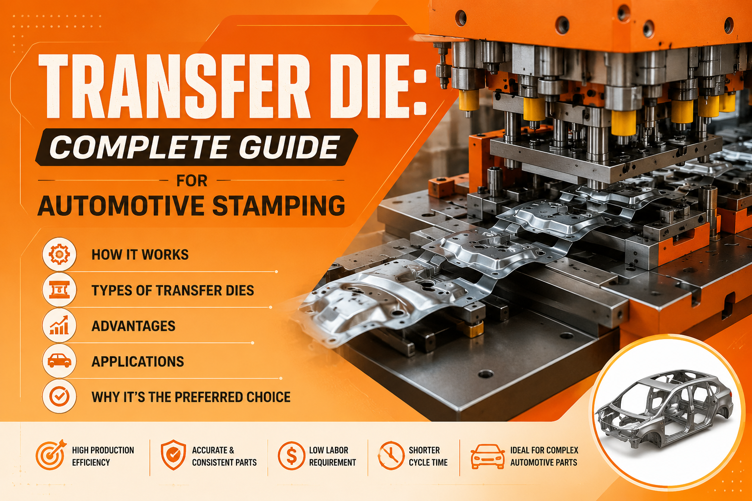
A transfer die is a multi-station metal stamping tool in which a pre-cut blank is automatically moved from one forming station to the next within a single press or a closely coupled press system. At each station, a specific operation is performed — drawing, piercing, trimming, flanging, or restrike — and the part is progressively formed to its final geometry.
The defining characteristic is that the blank is separated from the metal strip before forming begins. Unlike a progressive die — where the part remains connected to a strip carrier — a transfer die works with a free blank. This is what gives transfer dies their core capability: the ability to form complex three-dimensional geometries that strip-fed progressive dies simply cannot achieve.
Blank movement between stations is handled by an automated transfer mechanism — servo-driven transfer bars, mechanical fingers, or a 3-axis crossbar system — synchronised precisely with the press stroke.
How a Transfer Die Works
At each press stroke, every station operates simultaneously on a different blank. While one blank is being drawn at station one, the previous part is being pierced at station two, and the part before that is being flanged at station three — all in the same press stroke. This synchronised multi-station operation is what gives transfer dies their high productivity and dimensional consistency.
The sequence is simple: blank fed into station one → press closes, forming operation performed → press opens, transfer mechanism moves blank to next station → repeat until the finished part exits the final station.
Types of Transfer Dies
- Single-Press Transfer Die: All stations housed within one large-bed press. The most compact and cost-efficient configuration — the most common arrangement in Tier-1 and Tier-2 automotive supply.
- Tandem-Linked Transfer Die: Stations distributed across two or more synchronised presses. Used when the part is too large for a single press bed or when individual station tonnage exceeds single-press capacity.
- Tri-Axis Transfer Die: Transfer mechanism moves blanks in three axes — lift, advance, and clamp. Used for parts with complex three-dimensional transfer paths where standard two-axis finger transfer is insufficient.
- Servo Transfer Die: Transfer mechanism driven by servo motors, allowing timing and stroke to be programmed independently of the press stroke. Increasingly standard on modern automotive press lines for maximum flexibility and speed.
Transfer Die vs Progressive Die
Progressive Die: Remains in strip
Progressive Die: Limited — part stays in-plane
Progressive Die: Lower — skeleton is scrap
Progressive Die: Low to medium
Progressive Die: Lower
Progressive Die: 20–100+ spm
Progressive Die: Brackets, clips, shallow forms
Transfer Die vs Tandem Die
Tandem Die: Multiple individual presses
Tandem Die: Large to extra-large outer panels
Tandem Die: Large footprint
Tandem Die: Very High
Tandem Die: High
Tandem Die: Bonnets, doors, roofs, quarter panels
Key Components of a Transfer Die
- Die shoes and holders: Cast iron structural backbone that carries all working components and transmits forming loads to the press.
- Draw die inserts: D2 tool steel working surfaces hardened to 58–62 HRC, machined to AutoForm-compensated profiles to pre-correct for springback.
- Pierce and trim inserts: Cutting tools ranging from D2 tool steel for mild steel to tungsten carbide for AHSS and UHSS applications.
- Pressure pads and nitrogen cylinders: Control material flow and blank holder force during forming — critical for process stability on high-strength grades.
- Transfer mechanism: Servo fingers or crossbar systems that move blanks between stations with precision. One of the most intricate engineering elements of the entire die system.
- Guide system: Guide posts, bushings, and heel blocks that maintain upper-to-lower die alignment throughout the press stroke.
Typical Automotive Applications
- A-pillar and B-pillar reinforcements
- Rocker panel inner and reinforcements
- Front and rear subframe brackets
- Suspension tower reinforcements
- Floor pan sections and crossmembers
- Door inner panels
- Engine mount and transmission tunnel brackets
- Battery tray sections for electric vehicles
- Seat back frames and height adjuster brackets
Advantages of Transfer Dies
- Complex part capability: Free-blank forming enables true 3D geometry — deep draws, multi-plane flanges, and complex spatial forms — impossible in progressive dies.
- High material utilisation: Pre-cut blanks eliminate strip skeleton waste. On AHSS and aluminium, this saving is significant over programme life.
- Dimensional consistency: All stations share a common die reference datum — tighter dimensional stack-up than a tandem line where each press introduces independent positioning variation.
- Compact footprint: A complete multi-station die operates within a single press bed — a fraction of the floor space of an equivalent tandem line.
- Operational simplicity: One press, one die set, one maintenance responsibility — significantly lower operational overhead than a multi-press tandem line.
Limitations of Transfer Dies
- Press requirement: A transfer press with an integrated transfer mechanism is required. Standard progressive or single-station presses cannot run transfer dies without significant modification.
- Tooling investment: Transfer die tooling costs more than progressive tooling, reflecting the additional design and manufacturing complexity of the multi-station transfer system.
- Part size limitation: Practical limits of approximately 800 to 1,000 mm in the transfer direction for single-press configurations. Larger parts require tandem-linked configurations.
- Changeover time: Changing a complete transfer die set takes longer than single-station or progressive tooling — a scheduling consideration for high-mix programmes.
Transfer Die Manufacturing Timeline
Duration: Weeks 1–2
Duration: Weeks 2–6
Duration: Weeks 5–10
Duration: Weeks 4–12
Duration: Weeks 10–20
Duration: Weeks 18–24
Duration: Weeks 22–30
Duration: Weeks 28–32
FAQs: Transfer Dies
What materials can a transfer die stamp? The full range of automotive sheet materials — mild steel, HSS up to 590 MPa, AHSS up to 980 MPa, UHSS up to 1180 MPa, aluminium alloys, and stainless steel. Material grade determines insert specification, surface treatment, and simulation requirements.
How many stations does a transfer die typically have? Between 3 and 10 stations depending on part complexity. A simple bracket may need 3 to 4 stations. A complex structural reinforcement with multiple flanges and numerous pierce holes may require 7 to 10 stations.
What press tonnage is required? Typically 400 tonnes for small mild steel bracket parts up to 2,500 tonnes or above for large AHSS structural parts. Press bed size must accommodate the complete die set — all stations end to end — with clearance for the transfer mechanism.
What is the typical production life of a transfer die? On mild steel with D2 inserts and regular maintenance — 500,000 to 1,000,000 strokes before major refurbishment. On AHSS grades at 780–1180 MPa — 150,000 to 400,000 strokes depending on insert material and coating specification.
What is the difference between a transfer die and a compound die? A compound die performs multiple operations simultaneously at a single station in one press stroke. A transfer die performs different operations at multiple stations sequentially. Compound dies suit high-volume simple flat parts. Transfer dies suit complex three-dimensional formed parts.
How is a transfer die maintained in production? Regular inspection of cutting edge condition, draw die surface for galling or wear, guide post and bushing clearances, nitrogen cylinder pressures, and transfer finger geometry. A planned preventive maintenance schedule at defined stroke intervals is essential for consistent part quality and die life.
Build Your Transfer Die Programme on Solid Engineering
A transfer die is a precision engineering system — not a commodity purchase. The quality of the tooling determines the quality, consistency, and cost of every part produced on it for the life of the programme.
At Dai-Ichi Tools, transfer die manufacturing is our core business. Since 2017, we have manufactured transfer dies for automotive OEMs and Tier-1 suppliers across India — for structural panels, inner body panels, chassis components, and seat structure parts — in material grades from mild steel to 1180 MPa UHSS.
Every Dai-Ichi transfer die programme includes:
- AutoForm R12 simulation — standard on every programme
- Springback compensation applied to machining models before first cut
- D2 and SKD11 tool steel inserts with PVD or TD coating for AHSS grades
- 5-axis machining on Shin Nippon Koki RB3M and RB4M VMCs
- In-house tryout on presses up to 1,600 tonnes
- CMM and FARO scanner dimensional validation before dispatch
- Full simulation, tryout, and inspection reports with every die
- Detailed programme schedule at order confirmation
Dai-Ichi Tools — Faridabad, India