

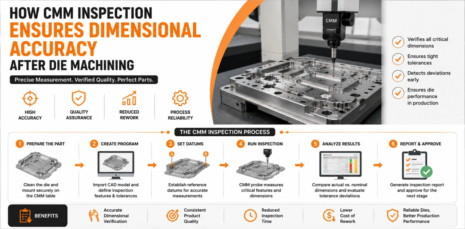
How CMM Inspection Ensures Dimensional Accuracy After Die Machining
A die that has been designed correctly, simulated thoroughly, and machined on a 5-axis VMC still requires one final validation before tryout. CMM inspection confirms that the machined geometry matches the design intent with the precision required for successful forming.
In automotive die manufacturing, CMM inspection is far more than a quality documentation process. It identifies machining deviations, verifies die readiness for tryout, and provides the dimensional baseline used during die correction.
What Is CMM Inspection?
A Coordinate Measuring Machine (CMM) is a precision measuring system that determines the exact XYZ coordinates of points on a component using contact or non-contact probes with micron-level accuracy.
In die manufacturing, CMM inspection is used to verify AutoForm-compensated die face geometry, guide post bore positions, insert pocket dimensions, and dimensional accuracy of tryout sample parts.
At Dai-Ichi Tools, inspections are performed using a Sheffield Apollo CMM with a measuring volume of 3,300 × 2,000 × 1,500 mm, allowing complete transfer die components and door inner panel tooling to be inspected in a single setup.
CMM Inspection After Die Machining
Die face geometry accuracy: Draw die and punch surfaces are measured against the AutoForm CAD model. Deviations greater than ±0.05 mm are identified and corrected before assembly.
Guide post bore verification: Bore position and diameter are inspected to ensure proper guide alignment and minimise wear during production.
Insert pocket inspection: Pocket depth, position, and orientation are verified to maintain hole location and trim accuracy.
Cam mechanism verification: Cam driver angles, travel distances, and return positions are measured to ensure accurate off-axis forming operations.
CMM Inspection of Tryout Sample Parts
Following physical tryout, CMM inspection evaluates every customer-defined measurement point, along with additional springback-sensitive locations identified during AutoForm simulation.
- Identify dimensions within tolerance.
- Highlight out-of-tolerance measurement points.
- Detect systematic springback trends.
- Support targeted die corrections instead of trial-and-error adjustments.
Detailed CMM reports allow engineers to identify exactly which die surfaces, inserts, or process parameters require correction before the next tryout iteration.
FARO Scanner Inspection
In addition to CMM inspection, Dai-Ichi Tools uses the FARO Quantum X.E 3D Scanner to capture complete die face and formed part geometry. Unlike point-based CMM measurement, FARO scanning generates full-surface deviation maps for comprehensive geometry verification.
FARO inspection is especially valuable for validating springback-compensated die surfaces and inspecting automotive outer panels where complete surface accuracy is essential.
FAQs
How does CMM inspection differ from FARO scanner inspection? CMM provides extremely accurate point measurements (typically ±0.002–0.005 mm) for critical features, while FARO scanning delivers complete surface coverage with slightly lower point accuracy (typically ±0.025–0.05 mm). Together they provide comprehensive dimensional validation.
Can CMM inspection replace physical tryout? No. CMM verifies machining accuracy but cannot predict real material behaviour during forming. Physical tryout remains essential for validating production performance.
What CMM reports does Dai-Ichi Tools provide? Every die programme includes die face verification reports, customer dimensional inspection reports, and FARO surface scan data where required.
Transfer and Tandem Die Specialists
Sheffield Apollo CMM and FARO Quantum X.E inspection on every programme — Dai-Ichi Tools, Faridabad, India.
Request a CMM-Validated Die Quotation →