Lead time is one of the first questions every automotive programme manager asks when a new die development is on the table. And for good reason, transfer die manufacturing sits on the critical path of almost every new vehicle program. A delay in tooling delivery means a delay in SOP, which in the automotive supply chain translates directly into customer penalties, lost production slots, and damaged commercial relationships. The honest answer is that transfer die manufacturing lead time ranges from 16 weeks to 32 weeks depending on part complexity, steel grade, number of forming stations, and the supplier's internal capacity. But that range is meaningless without understanding what actually happens inside those weeks — and where the timeline gets compressed or extended. At Dai-Ichi Tools, we manufacture 400+ dies annually for automotive OEMs and Tier-1 suppliers. This guide breaks down the complete transfer die manufacturing timeline, stage by stage, so you can plan your program accurately and ask the right questions of your tooling supplier.
Why Transfer Die Lead Time Is Different From Other Tooling
Before breaking down the timeline, it is worth understanding why transfer dies take longer to manufacture than progressive dies or single-station tools.
A transfer die is not one tool — it is a system of multiple integrated die stations, a transfer mechanism, and a press automation interface, all of which must function together with micron-level precision. Each station must be individually designed, machined, heat-treated, and assembled and then the entire system must be validated together in a tryout press before delivery.
The interdependency between stations means that a design change at station two can affect the blank presentation at station three, which cascades downstream. This makes transfer die development inherently more complex to manage than a series of standalone tools — and that complexity is reflected in the lead time.
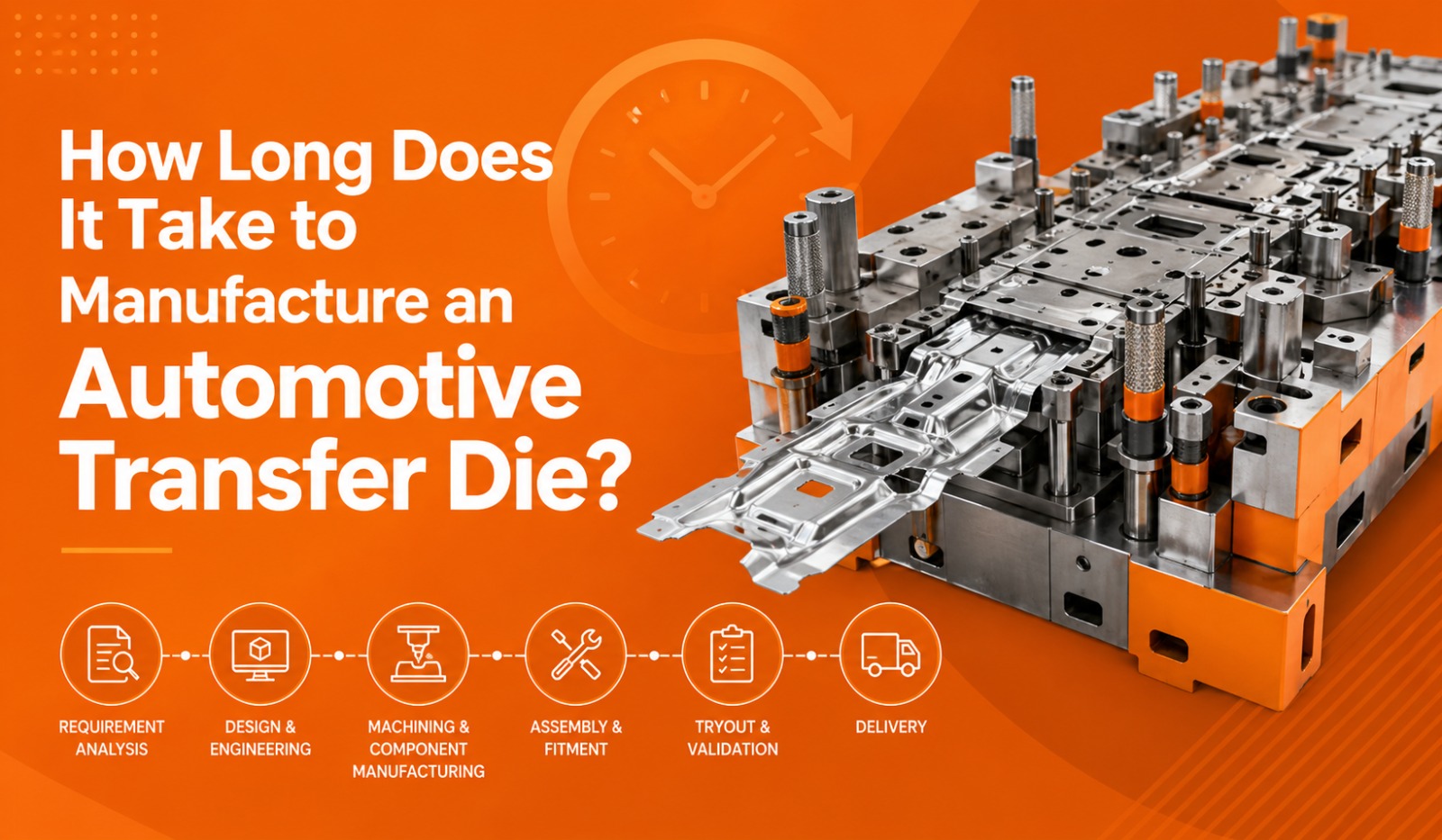
The Complete Transfer Die Manufacturing Timeline
Stage 1: Feasibility Analysis and DFM Review (Weeks 1–2)
Every transfer die programme begins with a feasibility study. At this stage, the die manufacturer reviews the part drawing, 3D model, material specification, and annual volume to determine:
- Optimal press direction and draw depth
- Number of forming stations required
- Blank shape and approximate blank size
- Material flow direction and transfer finger clearance zones
- Potential split, wrinkle, or springback risk areas
This is also the stage where AutoForm simulation begins. Early simulation at feasibility catches part geometry issues while they are still cheap to fix — before any die design work has been committed to.
What can delay this stage: Incomplete or changing part data from the customer, late material grade confirmation, and unclear press specifications from the end customer's production plant.
Stage 2: Die Face Design and Simulation (Weeks 2–6)
Once feasibility is approved, the die face design begins. This is the engineering core of the entire programme — the work that determines whether the finished die will produce a dimensionally correct, defect-free part. Die face design includes:
- Draw die addendum geometry and binder surface design
- Draw bead layout and geometry
- Blank holder geometry and pressure pad design
- Station-by-station forming sequence definition
- Transfer finger clearance zones designed into the addendum
AutoForm simulation runs in parallel with die face design, validating each geometry iteration before it is finalised. Springback analysis is completed at this stage, and die geometry compensation is applied to the machining model so that springback is corrected before the first cut of steel is made.
What can delay this stage: Multiple simulation iterations required for complex parts, customer DR (design review) approval cycles, and late engineering changes to the part drawing.
Stage 3: Detailed 3D Die Design (Weeks 5–10)
With the die face model validated and approved, the full 3D die design begins. This is where the complete mechanical structure of the die is engineered — every cast iron or steel component, every standard, every guide, every insert, every nitrogen cylinder and spring, and every transfer finger interface.
Key design outputs at this stage include:
- Complete 3D assembly models for all die stations
- Cast structure design for die shoes, holders, and pads
- Standard selection — punches, bushings, lifters, guide posts, heel blocks
- Strip layout drawing showing part progression through all stations
- 2D manufacturing drawings for all machined components
- Bill of materials for procurement
This stage also covers the transfer mechanism design — the finger geometry, stroke, and timing that will move the blank from station to station. Transfer finger design must account for part geometry, blank weight, transfer speed, and clearance to die components at all positions in the press stroke.
What can delay this stage: Complex part geometry requiring extensive insert design, customer-specified standard brands with long procurement lead times, and die design changes driven by late simulation feedback.
Stage 4: Material Procurement and Casting (Weeks 4–12)
Running in parallel with die design, material procurement and casting is frequently the longest lead time item in transfer die manufacturing — and the one most often underestimated by programme planners. Transfer die components require:
- Cast iron die shoes and holders: Typically GG25 or GG30 grey cast iron for large structural components. Casting, rough machining, and stress relieving typically takes 6–10 weeks from order placement.
- Tool steel inserts: D2, SKD11, or equivalent for punch and die insert sections. Procurement, rough machining, and heat treatment to 58–62 HRC typically takes 4–8 weeks.
- Standard components: Guide posts, bushings, nitrogen cylinders, lifters, heel blocks. These are typically available from stock if standard catalogue items are specified.
The critical path risk is cast iron. If casting orders are placed late — because design was not sufficiently advanced to release casting drawings — the entire programme timeline shifts right. Experienced die manufacturers release preliminary casting drawings at the earliest possible design stage to protect this timeline.
What can delay this stage: Late casting drawing release, foundry capacity constraints, imported standard components with long delivery lead times, and material grade changes late in the design process.
Stage 5: CNC Machining (Weeks 10–20)
CNC machining is the most resource-intensive and time-consuming stage of transfer die manufacturing. For a complex multi-station transfer die, total machining time across all components can run to several hundred machine hours across 3-axis and 5-axis VMCs.
Machining operations for a transfer die programme typically include:
- Rough machining of cast iron die shoes and holders after stress relief
- Semi-finish and finish machining of die faces to AutoForm-compensated geometry
- 5-axis machining of complex draw punch and die insert profiles
- High-speed finishing of draw die addendum surfaces to Ra 0.8 or better
- Machining of all punch, pierce, flange, and trim inserts
- Drilling and reaming of all guide post and bushing bores
- Machining of all transfer finger mounting interfaces
At Dai-Ichi Tools, this work is carried out on Shin Nippon Koki 5-axis VMCs (3000 × 2000 mm and 4000 × 2500 mm), KAO-MING and JIUH-YEH 3-axis VMCs, providing the machine capacity to run large transfer die programmes without the bottlenecks that constrain smaller toolrooms.
What can delay this stage: Machine capacity conflicts with concurrent programmes, casting defects requiring rework, design changes issued after machining has started, and insert heat treatment delays.
Stage 6: Bench Work, Assembly, and Spotting (Weeks 18–24)
Once machined components arrive at the bench, skilled die makers assemble each station and perform the critical hand-fitting work that CNC machining alone cannot achieve. This includes:
- Fitting and lapping of all mating die faces
- Spotting of draw dies using the spotting press to achieve full contact area
- Fitting of all punches, bushings, guides, and standards
- Installation and adjustment of nitrogen cylinders and pressure pads
- Assembly and initial adjustment of transfer finger mechanisms
- Fitting and checking of all trim and pierce inserts
Spotting — the process of applying marking compound to die faces and pressing them together to identify high contact points — is repeated iteratively until full bearing contact is achieved across the draw die face. For complex draw dies, this process alone can take several days of skilled benchwork per station.
What can delay this stage: Machining inaccuracies requiring rework, cast iron porosity or defects found during fitting, and unavailability of skilled die makers during concurrent program peaks.
Stage 7: Tryout and Die Prove-Out (Weeks 22–30)
Physical tryout is the final validation stage — the point where the completed die set is run in a tryout press under real forming conditions to produce actual stampings. At Dai-Ichi Tools, tryout is conducted on in-house presses ranging from 800 tonnes to 1,600 tonnes, meaning customers do not face the delays and logistical complications of third-party tryout facilities.
A typical transfer die tryout sequence involves:
- Initial setup and first hit to check for clearance issues and component contact
- First blank forming run to assess split, wrinkle, and dimensional condition
- AutoForm comparison measuring actual springback against simulation prediction
- Die correction based on tryout findings shimming, welding, re-machining
- Second and third tryout runs to validate corrections
- Final dimensional inspection using CMM and FARO scanner
- Process window validation confirming the die runs stably across the acceptable range of press and material parameters
- Customer approval samples produced and submitted
For well-simulated programs with clean machining, first-time-right tryout or single-correction tryout is achievable. For complex parts or programs where simulation was not completed rigorously, multiple tryout cycles add 2–6 weeks to the timeline.
What can delay this stage: Significant springback deviation from simulation prediction, material property variation in tryout blanks, customer approval delays, and dimensional issues requiring extensive die rework.
Stage 8: Final Inspection, Documentation, and Dispatch (Weeks 28–32)
Before a transfer die leaves the toolroom, it undergoes final inspection and documentation. This includes:
- CMM dimensional report on approved sample parts
- FARO scanner die face inspection to confirm machined geometry
- Die standard checklist — all components verified to drawing
- Tryout report documenting all corrections made during prove-out
- AutoForm simulation report — final version with springback compensation record
- Process parameter sheet — recommended press settings for production
- Spare parts list and first-fill spare parts supply
Transfer Die Lead Time Summary
Typical Duration: Weeks 1–2
Typical Duration: Weeks 2–6
Typical Duration: Weeks 5–10
Typical Duration: Weeks 4–12
Typical Duration: Weeks 10–20
Typical Duration: Weeks 18–24
Typical Duration: Weeks 22–30
Typical Duration: Weeks 28–32
Key Factors That Affect Transfer Die Lead Time
Part complexity: A 3-station transfer die for a simple bracket and an 8-station die for a deep-draw structural reinforcement are fundamentally different in design, machining, and tryout effort. Station count is the single strongest predictor of lead time.
Steel grade: High-strength steels above 590 MPa and AHSS grades require more extensive simulation, more careful die face geometry, and typically more tryout correction for springback adding time at both the design and tryout stages.
Customer DR cycles: Every design review that requires significant rework resets the downstream schedule. Programmes with streamlined, well-prepared DR processes consistently deliver faster than those with protracted approval cycles.
Supplier machine capacity: A toolroom running at 90% machine utilisation will always push non-urgent work. Understanding your supplier's current loading before placing an order is essential for realistic timeline planning.
Simulation investment: Programmes with rigorous upfront AutoForm simulation consistently reach first-time-right or single-correction tryout. Programmes without simulation routinely require 3-5 tryout cycles adding 4-8 weeks to the programme timeline.
FAQs: Transfer Die Manufacturing Lead Time
What is the minimum lead time for a transfer die?For a relatively simple 3 to 4 station transfer die on a mild steel part with clean part data and a streamlined DR process, 16 to 18 weeks is achievable at a well-equipped toolroom. Complex 6 to 8 station dies on AHSS grades should be planned at 26 to 32 weeks minimum.
What is the most common cause of transfer die delays?Late casting drawing release is the single most common cause of programme delays in transfer die manufacturing. Cast iron procurement and stress-relief cycles are fixed-duration activities that cannot be compressed — so any delay in releasing casting drawings pushes the entire programme timeline.
Can the design and machining stages run in parallel?Partially. Casting drawings can be released before the full die design is complete, and rough machining of cast components can begin before finish machining drawings are available. However, finish machining cannot begin until the die face design and simulation are finalised and approved.
How does AutoForm simulation affect lead time?Simulation adds 1 to 3 weeks to the front end of the programme. However, it consistently saves 3 to 8 weeks at the tryout stage by reducing the number of correction cycles required. The net effect of simulation on total programme lead time is almost always a reduction of 2 to 6 weeks.
What should I provide to my die supplier to avoid delays?Provide finalised 3D part data, confirmed material grade and specification, annual volume, press specification (bed size, tonnage, stroke, transfer system type), and any customer-specific die standards at the time of order placement. Late or changing inputs are the leading cause of avoidable programme delays.
Does Dai-Ichi Tools provide a programme schedule at order placement?Yes. Dai-Ichi Tools provides a detailed programme schedule broken down by stage at the time of order confirmation — with agreed milestone dates for feasibility sign-off, die face design approval, casting release, machining completion, tryout start, and customer approval sample submission.
Plan Your Transfer Die Program With Confidence
Transfer die lead time is not a mystery — it is a predictable outcome of the decisions made at the start of the program. The right supplier, rigorous simulation from day one, clean part data at order placement, and a streamlined DR process are the four inputs that consistently deliver tooling on time and within budget.
At Dai-Ichi Tools, we have built our manufacturing process around these principles and we back them with in-house machining capacity up to 5-axis simultaneously, tryout presses up to 1,600 tonnes, and Auto-Form R12 simulation on every program.
If you have a transfer die programme coming up and need an accurate timeline and quotation, our engineering team is ready to review your part data and give you a programme schedule you can actually plan around.
What you get with every Dai-Ichi transfer die programme:
- Detailed programme schedule issued at order confirmation
- AutoForm R12 simulation as a standard deliverable not optional
- In-house tryout on presses up to 1,600 tonnes no third-party delays
- CMM and FARO scanner dimensional validation before dispatch
- Full simulation, tryout, and inspection reports supplied with the die
- 400+ dies manufactured annually with 15+ OEM and Tier-1 customers
Dai-Ichi Tools - Faridabad, India