High-strength steel has fundamentally changed the rules of automotive die manufacturing. What worked reliably for mild steel and conventional high-strength grades below 590 MPa does not simply scale up to 780 MPa, 980 MPa, or 1180 MPa. The forming forces are higher, the springback is more severe, the wear on tooling is more aggressive, and the margin for error at every stage, design, simulation, machining, tryout — is significantly narrower.
For automotive OEMs and Tier-1 suppliers using advanced high-strength steels (AHSS) and ultra-high-strength steels (UHSS) to meet crash performance and lightweighting targets, the quality of the die is not a background variable. It is one of the primary determinants of whether the program delivers dimensionally correct parts at production volume — or spends months in a costly tryout loop.
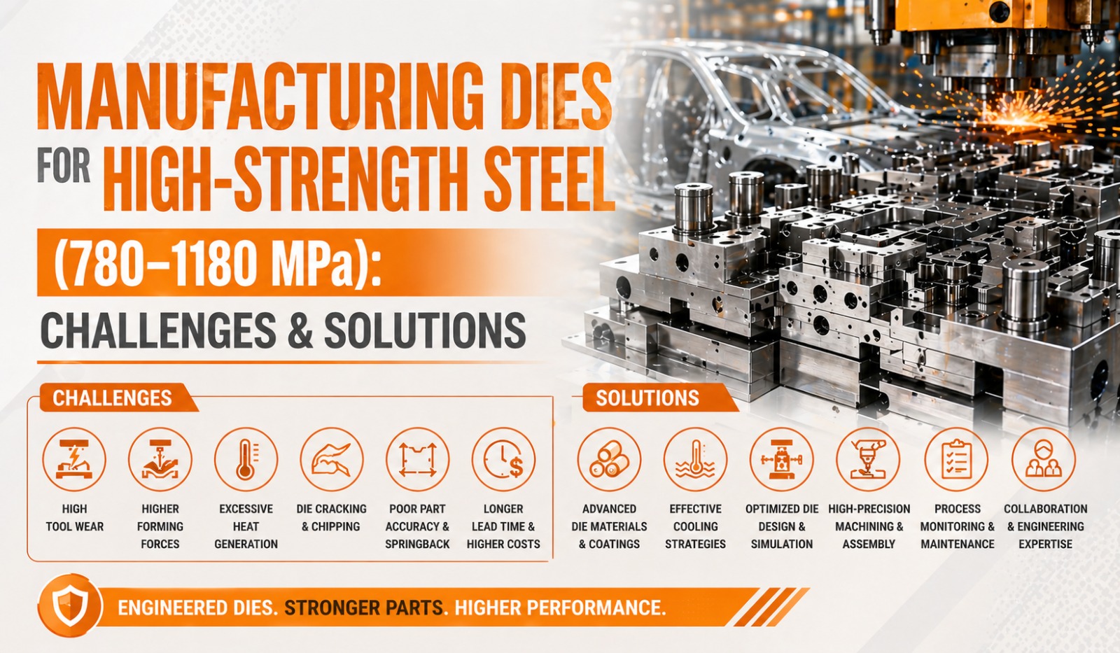
At Dai-Ichi Tools, we manufacture dies for structural panels in the 780–1180 MPa range as a core capability. This article covers every major challenge in this category of tooling and the engineering solutions that resolve them so your program team understands exactly what is required to get it right.
Why High-Strength Steel Changes Everything in Die Manufacturing
Standard automotive die design principles were developed primarily around mild steel (up to 270 MPa) and conventional HSS grades up to 590 MPa. In this range, springback is manageable, forming forces are predictable, tool wear is moderate, and die materials like GG25 cast iron perform reliably for the working surfaces.
At 780 MPa and above, every one of these assumptions breaks down:
- Forming forces increase by 2x to 4x compared to mild steel, loading die structures and press equipment far beyond conventional design parameters
- Springback becomes severe and often unpredictable without rigorous simulation — dimensional deviations of 5 to 15 mm after forming are not uncommon on first tryout
- Tool wear accelerates dramatically, cast iron working surfaces that last millions of strokes on mild steel may show measurable wear within tens of thousands of strokes on 1180 MPa material
- Fracture risk during forming increases sharply because AHSS and UHSS grades have limited elongation at high strength levels
- Heat generation during forming becomes significant at the highest strength levels, affecting both part quality and die life
These are not incremental challenges. They require a fundamentally different approach to die design, material selection, simulation methodology, and tryout strategy.
Challenge 1: Severe Springback and Dimensional Deviation
Springback is the elastic recovery of the sheet metal after the forming load is removed. In mild steel, springback is modest and relatively easy to compensate empirically. In 980 MPa dual-phase steel, springback of 8 to 15 degrees on a simple flange is common. In 1180 MPa martensitic steel, dimensional deviations after forming can render a part completely out of specification without deliberate die geometry compensation.
The challenge is that springback in AHSS is not only larger — it is more sensitive to material property variation. A change in yield strength of ±30 MPa within the acceptable coil specification can shift springback by 1 to 3 mm on a critical surface. This means that a die that passes tryout on the first coil lot may produce out-of-tolerance parts on the next delivery.
Solution: AutoForm Springback Simulation and Die Compensation
The only reliable solution to AHSS springback at this strength level is rigorous forming simulation with full springback prediction and die geometry compensation applied before machining begins. At Dai-Ichi Tools, AutoForm R12 is used to:
- Predict springback magnitude and direction at every measurement point on the part
- Apply inverse springback compensation to the die face geometry — overbending the part in the die so that it springs back to the correct nominal geometry
- Test compensation across the full range of incoming material property variation — not just at the nominal grade specification
- Define a process window within which springback remains within acceptable tolerance despite coil-to-coil material variation
Programs that attempt to correct AHSS springback empirically at tryout — without prior simulation compensation, routinely spend 4 to 8 additional tryout cycles chasing dimensional compliance. The simulation investment at the front end of the program is not optional for this material category.
Challenge 2: Accelerated Die Wear and Reduced Tool Life
At 780 MPa and above, the contact pressure between the sheet metal and the die working surfaces during forming is sufficient to cause rapid wear on conventional die materials. Cast iron inserts that perform acceptably on mild steel stampings show measurable surface degradation within 30,000 to 80,000 strokes on 1180 MPa material — far below the 500,000 to 1,000,000 stroke targets expected of production tooling.
Wear manifests primarily in three ways on AHSS dies:
- Galling: adhesive wear where material from the sheet transfers to the die surface, eventually scratching subsequent parts
- Abrasive wear: progressive removal of die surface material by the hard oxide layer on AHSS coil surfaces
- Edge chipping: micro-fracture of trim and pierce punch cutting edges under the high cutting forces required for UHSS grades
Solution: Premium Tool Steel Inserts and Surface Treatments
The solution to AHSS wear is a combination of correct die insert material selection and appropriate surface treatment. At Dai-Ichi Tools, dies for 780–1180 MPa materials are built with:
Die insert materials:
- D2 tool steel (1.2379) hardened to 60–62 HRC for draw die working surfaces
- SKD11 equivalent grades for complex profile inserts requiring EDM finishing
- Carbide inserts for trim and pierce operations on 980–1180 MPa material where edge life on tool steel is insufficient
- Powder metallurgy tool steels for the most severe wear applications
Surface treatments:
- Physical vapour deposition (PVD) coatings, TiN, TiCN, or CrN applied to draw and flange surfaces to reduce friction and prevent galling
- TD (Thermal Diffusion) vanadium carbide coating for the highest wear resistance on trim and pierce inserts
- Hard chrome plating on guide surfaces and transfer finger contact zones
The combination of correct substrate hardness and appropriate surface treatment can extend die life on 1180 MPa material by a factor of 3 to 5 compared to uncoated tool steel inserts.
Challenge 3: High Forming Forces and Die Structural Integrity
Forming 1180 MPa steel requires press forces 3 to 4 times higher than forming equivalent thickness mild steel. These forces are transmitted through the entire die structure — from the working surface inserts through the holders and shoes to the press bolster. A die structure that is adequate for conventional HSS will deflect, distort, or fail prematurely under AHSS forming loads.
Structural inadequacy in a die manifests as:
- Bending deflection of draw die shoes under peak forming load — causing dimensional variation across the part width
- Premature fatigue cracking of cast iron structures at stress concentration points
- Guide post and bushing wear from lateral loads generated by asymmetric forming forces
- Fastener loosening and insert shifting under repeated high-load forming cycles
Solution: Engineered Die Structures for High-Load Applications
Dies for 780–1180 MPa materials at Dai-Ichi Tools are designed with AHSS forming loads calculated explicitly in the design phase:
- Die shoe section sizes and rib geometries are calculated to limit deflection under peak forming load to within acceptable thresholds
- Cast iron grade is upgraded from GG25 to GG30 or nodular iron (GGG60) for the highest load applications
- Critical structural sections are designed with FEA-informed rib layouts to maximise stiffness-to-weight ratio
- Guide post diameters and bushing lengths are increased beyond standard catalogue recommendations to handle the lateral load components present in asymmetric AHSS forming operations
- Insert retention systems — dowels, keys, and fasteners — are engineered for the actual pull-out and shear forces present at AHSS forming loads, not scaled from mild steel precedents
Challenge 4: Fracture and Edge Cracking During Forming
AHSS and UHSS grades have significantly lower elongation at break compared to mild steel. Where mild steel may have 35–45% total elongation, 980 MPa dual-phase steel typically has 8–12% and 1180 MPa martensitic steel may have only 4–6%. This narrow forming window means that die geometry errors, sharp radii, or incorrect blank holder forces that would produce minor thinning on mild steel can cause outright fracture on AHSS.
Edge cracking fracture initiating from the sheared or laser-cut blank edge — is a specific and common failure mode in AHSS forming that has no real equivalent in mild steel stamping. The sheared edge of a high-strength steel blank has a damaged microstructure zone from the cutting process, and this zone has significantly lower ductility than the base material. When forming strains are concentrated at the blank edge as they frequently are in flange and stretch operations fracture initiates at the sheared edge before the forming limit of the base material is reached.
Solution: Geometry Optimisation, Blank Preparation, and Process Control
Addressing fracture and edge cracking on AHSS requires action at multiple levels:
- Die radius optimisation: AutoForm simulation is used to identify all zones where thinning approaches the forming limit, and die radii are increased or re-profiled to redistribute strain away from critical zones
- Draw bead geometry: Draw beads are redesigned for AHSS to reduce restraining force per unit length, preventing over-stretching of the material in draw operations
- Blank edge quality specification: Laser cutting or fine blanking is specified for blank edges that will be subject to stretch-flange operations — eliminating the damaged microstructure zone that initiates edge cracking on sheared blanks
- Blank holder force control: Nitrogen cylinder pressures and binder geometry are tuned in simulation and validated at tryout to keep blank holder force within the narrow window that prevents both wrinkling and fracture on AHSS
Challenge 5: Trim and Pierce Operations on UHSS
Trimming and piercing 980–1180 MPa material places extraordinary demands on cutting tool geometry and material. The cutting forces required are 3 to 4 times those for mild steel of equivalent thickness, and the abrasive wear on cutting edges is severe. Standard punch and die clearances optimised for mild steel produce burr, rollover, and secondary shear on UHSS that are unacceptable for automotive structural parts.
Solution: Engineered Cutting Geometry and Carbide Tooling
- Cutting clearance: Clearance between punch and die is increased to 12–16% of material thickness for UHSS grades, compared to 8–10% for mild steel reducing cutting forces and improving edge quality
- Shear angle: Shear angle is applied to trim and pierce punches to reduce peak cutting force and shock load on the die structure
- Carbide inserts: Tungsten carbide inserts are used for trim and pierce operations on 1180 MPa material where tool steel cutting edges show unacceptable wear rates within the first production runs
- Step cutting: On long trim lines, step cutting geometry is designed into the trim steel to break the trim operation into sequential segments — reducing instantaneous peak force and press snap-through
Challenge 6: Process Window Stability in Production
Even after a die has been successfully trialled and approved, maintaining dimensional consistency across production volume on 1180 MPa material is more demanding than on mild steel. The narrow forming window of UHSS means that process parameter drift — press speed variation, lubrication inconsistency, coil property variation between heats — produces dimensional variation that would be invisible on mild steel tooling.
Solution: Defined and Documented Process Windows
At Dai-Ichi Tools, every die for 780–1180 MPa material is delivered with a fully validated process window document covering:
- Recommended and acceptable range of blank holder force
- Press speed range within which part quality is maintained
- Lubrication type, application method, and quantity specification
- Material property acceptance criteria for incoming coil inspection
- Measurement plan identifying the 8 to 12 dimensional features most sensitive to process variation
This document allows the customer's production team to set up the process correctly from day one of production and to diagnose dimensional drift rapidly when it occurs — rather than discovering it through warranty returns.
AHSS Die Manufacturing — Key Parameters Summary
HSS (590 MPa): Moderate
AHSS (780–980 MPa): High
UHSS (1180 MPa): Very High
HSS (590 MPa): 2x
AHSS (780–980 MPa): 3x
UHSS (1180 MPa): 4x
HSS (590 MPa): Tool steel optional
AHSS (780–980 MPa): Tool steel required
UHSS (1180 MPa): Carbide recommended
HSS (590 MPa): Recommended
AHSS (780–980 MPa): Required
UHSS (1180 MPa): Essential
HSS (590 MPa): Strongly recommended
AHSS (780–980 MPa): Mandatory
UHSS (1180 MPa): Mandatory
HSS (590 MPa): 2–3
AHSS (780–980 MPa): 3–4 with simulation
UHSS (1180 MPa): 2–3 with simulation
HSS (590 MPa): High
AHSS (780–980 MPa): Medium
UHSS (1180 MPa): Lower — managed with coating
HSS (590 MPa): Low
AHSS (780–980 MPa): Medium-High
UHSS (1180 MPa): High
FAQs: Dies for High-Strength Steel
What is the difference between HSS, AHSS, and UHSS in die manufacturing terms?In practical die manufacturing terms, HSS (high-strength steel up to 590 MPa) requires more robust die structures and recommended simulation but can often be approached with upgraded conventional die design. AHSS (780–980 MPa) requires mandatory simulation, premium tool steel inserts, surface coatings, and engineered die structures. UHSS (1180 MPa and above) requires all of the above plus carbide tooling for trim and pierce operations, the most rigorous springback compensation, and the tightest process window management.
Can existing mild steel dies be modified to run AHSS material?In most cases, no, not reliably or safely. Dies designed for mild steel have insufficient structural stiffness for AHSS forming loads, inadequate insert materials for AHSS wear rates, and die geometry that has not been compensated for AHSS springback. Attempting to run AHSS on mild steel tooling typically results in rapid die wear, dimensional rejection, and potential structural failure of the die.
How much more does a die for 1180 MPa material cost compared to mild steel tooling?A die for 1180 MPa material typically costs 35 to 60% more than an equivalent die for mild steel, reflecting the higher-grade insert materials, surface treatments, more extensive simulation, and additional tryout effort required. However, the cost of inadequate tooling in rework, scrap, and program delay consistently exceeds this premium many times over.
Does AutoForm accurately predict springback for 1180 MPa martensitic steel?AutoForm prediction accuracy for UHSS springback has improved significantly with recent software versions and updated material cards. With correct material card selection and calibrated simulation settings, AutoForm R12 achieves springback prediction accuracy sufficient for die compensation on 1180 MPa grades in the majority of part geometries. Complex parts with severe three-dimensional springback may require iterative simulation and physical measurement to refine the compensation model.
What surface coating does Dai-Ichi Tools recommend for 980 MPa draw dies?For draw and flange operations on 980 MPa DP steel, Dai-Ichi Tools typically specifies TiCN PVD coating on D2 tool steel inserts hardened to 60–62 HRC. For the most severe wear applications and for 1180 MPa grades, vanadium carbide TD coating or tungsten carbide inserts are evaluated on a case-by-case basis depending on part geometry and production volume.
How does Dai-Ichi Tools validate dimensional compliance on AHSS parts?All AHSS die programs at Dai-Ichi Tools are validated using Sheffield Apollo CMM (3300 × 2000 × 1500 mm) and FARO Quantum X.E scanner. CMM inspection reports covering all customer-specified measurement points are provided as standard deliverables with every die approval submission.
Build Your AHSS Die Program on Engineering, Not Assumptions
High-strength steel at 780-1180 MPa does not forgive shortcuts in die design, simulation, or material selection. Every challenge outlined in this article has a proven engineering solution — but those solutions must be built into the program from the feasibility stage, not retrofitted at tryout when the costs are highest.
At Dai-Ichi Tools, structural panel dies in the 780–1180 MPa range are a core product category — not an edge case. Our team brings Auto-Form R12 simulation, premium tool steel and carbide insert capability, 5-axis machining to micron tolerances, and in-house tryout presses to 1,600 tonnes to every AHSS program we undertake.
If you have an AHSS or UHSS die program coming up whether transfer die, tandem die, or single-station — and you want to understand the engineering approach before committing budget, our team is ready to review your part data and provide a detailed technical proposal.
What every Dai-Ichi AHSS die program includes:
- AutoForm R12 springback simulation and die compensation standard on every AHSS program
- Premium D2 and SKD11 tool steel inserts with PVD or TD coating as required
- Engineered die structures calculated for AHSS forming loads
- Carbide trim and pierce inserts for 980–1180 MPa material
- Documented process window delivered with every die
- CMM and FARO scanner dimensional validation before dispatch
- In-house tryout on presses up to 1,600 tonnes, Faridabad, India
Dai-Ichi Tools - Faridabad, India