Every piece of sheet metal that is formed in a stamping die does the same thing the moment the press opens and the forming load is removed — it tries to return to its original flat shape. It never gets all the way back. But how far it gets back, and in which direction, determines whether the part that comes out of the die meets the customer's dimensional specification or fails it.
That elastic recovery is called springback. And in automotive metal stamping — particularly with the high-strength and advanced high-strength steels that now dominate body structure and chassis programmes — springback is one of the most significant, most costly, and most frequently underestimated engineering challenges in the entire die development process.
A part that springs back 8 degrees on a critical flange, or 3 mm on a reference surface, is a rejected part. A die that consistently produces rejected parts because springback was not properly predicted and compensated is a die that will spend months in a costly correction loop — eating programme budget, delaying SOP, and damaging the commercial relationship between tooling supplier and customer.
Understanding springback — what causes it, how it behaves across different materials and geometries, and how it is controlled — is essential knowledge for every stamping engineer, die designer, and programme manager working in automotive sheet metal.
At Dai-Ichi Tools, springback prediction and compensation is a core capability on every transfer die and tandem die programme. This guide covers the complete picture — from the physics of why springback happens to the simulation and tooling techniques used to control it in production.
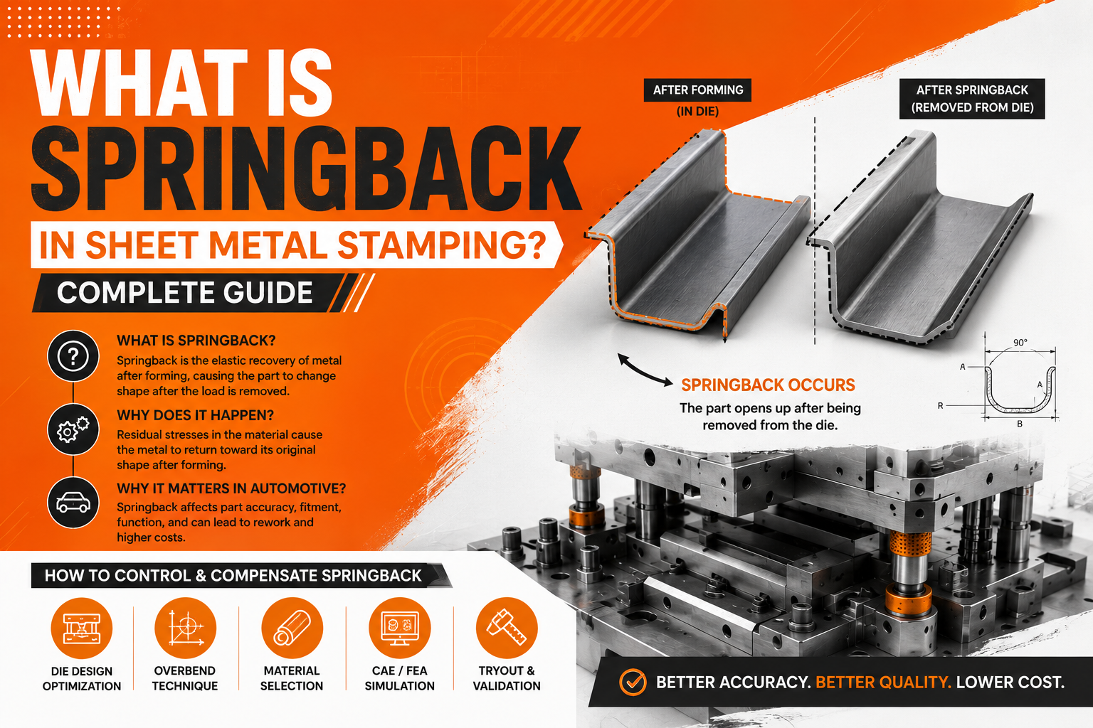
What Is Springback?
Springback is the elastic recovery of sheet metal after a forming load is removed. When a blank is formed in a stamping die, the material is subjected to plastic deformation — permanent shape change — combined with elastic deformation — temporary shape change that recovers when the load is removed.
When the press opens and the die load is released, the elastic component of the deformation recovers. The material springs back toward its original unformed shape. Because the plastic deformation remains, the part does not return fully to flat — but it does move away from the die geometry, and that movement is springback.
The result is a part whose geometry after springback differs from the die geometry that produced it. If the die was designed to the nominal part geometry without springback compensation, the part after springback will be out of tolerance — flanges at the wrong angle, surfaces at the wrong curvature, holes in the wrong position.
Springback is not a defect in the material or a failure of the process. It is a fundamental consequence of the elastic-plastic behaviour of all metallic materials under forming loads. It cannot be eliminated. It can only be predicted accurately and compensated deliberately in the die geometry.
The Physics of Springback
Understanding why springback happens requires a basic understanding of how sheet metal responds to forming loads.
When a metal blank is bent or drawn in a die, the material through its thickness is subjected to a through-thickness stress distribution. On the outside of a bend, the material is in tension — being stretched. On the inside of a bend, the material is in compression — being squeezed. At the neutral axis through the middle of the thickness, stress is theoretically zero.
When the forming load is removed, the elastic component of this stress distribution recovers. The tensile stress on the outer surface tries to contract — pulling the outer surface back toward its original length. The compressive stress on the inner surface tries to expand — pushing the inner surface back toward its original length. This recovery of the through-thickness stress gradient is what causes the part to spring back away from the die geometry.
The magnitude of springback is governed by the ratio of the material's yield strength to its elastic modulus — a material property relationship often expressed as the yield strength divided by Young's modulus (σy/E).
This ratio is the most important single predictor of springback severity:
- Mild steel (270 MPa): σy/E ≈ 0.0013 — low springback
- Conventional HSS (590 MPa): σy/E ≈ 0.0028 — moderate springback
- AHSS DP980 (980 MPa): σy/E ≈ 0.0047 — high springback
- UHSS (1180 MPa): σy/E ≈ 0.0056 — very high springback
- Aluminium 6xxx (300 MPa): σy/E ≈ 0.0043 — high springback despite lower strength
This is why high-strength steel grades produce more severe springback than mild steel — not because they are harder to deform, but because the ratio of their elastic recovery to their plastic deformation is higher. A 980 MPa dual-phase steel part will spring back 3 to 4 times as much as an equivalent mild steel part formed to the same geometry.
Types of Springback in Automotive Stamping
Springback does not manifest as a single, simple movement. In automotive stampings — which are complex three-dimensional shapes formed across multiple die stations — springback appears in several distinct forms, each with different effects on part dimensional compliance.
Angular Springback
The most straightforward form. After a flange or bend operation, the flange angle opens up by a predictable amount as the elastic stress gradient in the bend zone recovers. A flange formed to 90 degrees in the die might measure 94 degrees after springback on 590 MPa HSS, or 100 degrees on 980 MPa AHSS.
Angular springback is the most common cause of flange angle non-compliance in automotive stampings and the most straightforward to compensate — by over-bending the flange in the die to the angle that, after springback recovery, produces the correct nominal angle.
Wall Curl
Wall curl is a curvature that develops on the vertical walls of deep-drawn parts as a result of the material passing over the die entry radius during drawing. As the material is drawn over the die radius, it is first bent and then straightened — a bending-unbending cycle that produces a residual stress gradient through the thickness that causes the drawn wall to curl inward or outward after the forming load is released.
Wall curl is particularly problematic on parts with deep drawn walls and tight die entry radii. It is more severe on higher-strength materials and can cause significant dimensional deviation on parts where wall straightness is a critical assembly requirement.
Twist
Twist is a rotational springback — the part rotates about its longitudinal axis after forming. It occurs when the springback forces and moments across the part are asymmetric — when the elastic recovery on one side of the part is different in magnitude or direction from the elastic recovery on the other side.
Twist is the most difficult form of springback to predict and compensate because it is a three-dimensional phenomenon sensitive to subtle asymmetries in part geometry, material properties, and die contact conditions. Parts with complex three-dimensional geometry — L-shaped, Z-shaped, or hat-section structural parts — are particularly susceptible to twist springback.
Global Shape Deviation
In addition to localised angular and curl effects, the complete formed part may deviate from nominal shape across its entire surface — particularly on large, complex panels. This global shape deviation is the result of the springback forces and moments distributed across the entire part interacting with the part's three-dimensional stiffness. It is most apparent on large outer body panels — bonnets, roofs, and door outers — and on large structural parts with complex three-dimensional geometry.
Sidewall Springback
Sidewall springback is the elastic recovery of the draw punch sidewall contact pressure after the press opens. During drawing, the punch sidewall exerts normal pressure on the drawn wall, which compresses the material slightly. When the press opens and the punch withdraws, this pressure is released and the drawn wall springs away from the punch — slightly increasing the internal dimensions of the drawn form. This affects the accuracy of features formed on the drawn wall and must be accounted for in draw punch geometry.
How Material Grade Affects Springback Severity
The relationship between material grade and springback severity is one of the most practically important in automotive die design. As vehicle programmes increasingly specify AHSS and UHSS for body structure and chassis components, springback has become a primary design and tooling challenge — not a secondary consideration.
Severity: Very Low
Angular Error: 1–3°
Compensation: Empirical correction at tryout
Severity: Low
Angular Error: 2–4°
Compensation: Minor compensation
Severity: Moderate
Angular Error: 3–6°
Compensation: Simulation recommended
Severity: Moderate-High
Angular Error: 5–10°
Compensation: Simulation required
Severity: High
Angular Error: 8–14°
Compensation: Mandatory simulation compensation
Severity: Very High
Angular Error: 10–18°
Compensation: Mandatory simulation compensation
Severity: Extreme
Angular Error: 14–22°
Compensation: Full simulation compensation + restrike
Severity: High
Angular Error: 8–15°
Compensation: Simulation required
These angular error ranges are indicative for simple flange geometries on representative part sections. Complex three-dimensional parts with multiple interacting springback modes will show greater total dimensional deviation than these single-feature estimates suggest.
How Springback Affects Die Design
Springback affects die design at every forming station — not just the draw station. Understanding where and how springback must be addressed in the die design is fundamental to producing a die that delivers dimensional compliance from the first tryout.
At the Draw Station
Draw station springback — particularly wall curl and global shape deviation — is addressed by over-forming the part geometry in the die. The draw punch, draw die, and binder geometry are designed to a slightly exaggerated geometry so that after springback recovery, the part geometry matches the nominal drawing specification.
The challenge is determining exactly how much over-forming is required — and in what directions across a complex three-dimensional part. This cannot be determined reliably by experience or engineering judgement alone for AHSS grades. It requires simulation.
At the Flange Station
Flange station springback — angular springback — is addressed by designing the flange punch to over-bend the flange beyond the nominal angle by the predicted springback amount. For mild steel flanges, this compensation is straightforward — typically 2 to 5 degrees of over-bend. For 980 MPa AHSS flanges, the required over-bend may be 10 to 18 degrees — a compensation that must be derived from simulation data to be reliable.
At the Restrike Station
For complex AHSS parts where draw and flange station compensation alone cannot bring all measurement points into final tolerance, a dedicated restrike station is added to the die sequence. The restrike tool applies forming pressure across the complete part geometry simultaneously, coining out residual springback deviations from upstream stations and bringing the part to final dimensional compliance.
Methods Used to Control Springback
There is no single method that controls springback in all situations. Effective springback management in automotive stamping uses a combination of simulation, die geometry compensation, process parameter optimisation, and tooling design techniques — selected and combined based on the material grade, part geometry, and dimensional requirements of the specific programme.
Method 1 — AutoForm Simulation and Die Geometry Compensation
Simulation-based springback compensation is the most reliable and most widely used method for AHSS and UHSS programmes. AutoForm calculates the springback at every point on the part surface and applies an inverse compensation to the die geometry — modifying the die face so that the part springs back to the correct nominal geometry after forming.
The compensation process works as follows:
- AutoForm simulates the complete forming sequence and predicts the springback deviation at every measurement point
- The predicted springback deviation is applied inversely to the die geometry — surfaces that spring back inward are over-formed outward by the predicted deviation amount, and vice versa
- The compensated die geometry is used as the basis for the machining model
- After the first tryout, actual springback is measured and compared to the simulation prediction
- If residual deviation exists, a second compensation iteration is applied
At Dai-Ichi Tools, AutoForm springback compensation is standard on all AHSS programmes above 590 MPa. For well-simulated programmes on typical automotive structural parts, first-iteration compensation achieves dimensional compliance within ±0.5 to ±1.0 mm at all measurement points — a result that without simulation typically requires 3 to 5 tryout correction cycles to achieve.
Method 2 — Over-Bending
Over-bending — designing the die to form the part beyond the nominal angle or geometry by the expected springback amount — is the simplest and most direct method of springback compensation. It is effective for angular springback on simple flanges where the springback is predictable and consistent.
For mild steel and conventional HSS below 590 MPa, over-bending compensation values can be estimated from experience tables and adjusted at tryout without significant cost. For AHSS grades above 590 MPa, over-bending compensation must be derived from simulation — because the springback magnitude is too large and too sensitive to part geometry and material property variation to estimate reliably from experience.
Method 3 — Coining and Restrike
Coining applies very high local pressure to the bend zone — typically 3 to 5 times the normal forming pressure — to suppress the through-thickness stress gradient that causes springback. By plastically deforming the material through its full thickness at the bend, coining reduces the residual elastic stress gradient and consequently reduces springback significantly.
Coining is most effective on simple bend geometries where the punch can apply high pressure uniformly across the full bend zone. It is less effective on complex three-dimensional surfaces where uniform high pressure cannot be maintained across the entire part geometry.
Restrike — re-forming the part in a close-fitting tool after the primary forming operations — applies forming pressure across the complete part surface to correct residual springback deviations. Restrike is the standard approach for complex AHSS parts where draw and flange compensation alone is insufficient to achieve final dimensional compliance.
Method 4 — Draw Bead Optimisation
Draw beads increase the restraining force on the blank during drawing, which increases the plastic strain in the drawn walls and reduces the elastic component of the total strain — consequently reducing springback. Higher draw bead restraining force means more plastic deformation and proportionally less elastic recovery.
Draw bead geometry — height, width, and penetration — is optimised in AutoForm simulation to achieve the maximum feasible restraining force without causing splitting. For AHSS programmes, draw bead optimisation is one of the primary tools for managing wall curl and global shape deviation without adding restrike stations.
Method 5 — Blank Holder Force Optimisation
Blank holder force has a direct effect on springback — higher blank holder force increases through-thickness compressive stress in the drawn material, which partially offsets the tensile elastic stress gradient that causes springback. Optimising blank holder force — through nitrogen cylinder pressure adjustment or hydraulic cushion pressure programming — is a process-level method of reducing springback without modifying the die geometry.
Blank holder force optimisation is most effective as a fine-tuning tool after die geometry compensation has addressed the primary springback. It is particularly useful for reducing part-to-part springback variation caused by coil-to-coil material property variation — by adjusting blank holder force to compensate for incoming material strength variation, the process window for dimensional compliance can be widened.
Method 6 — Part Geometry Modification
Some springback problems are most efficiently resolved by modifying the part geometry rather than compensating the die geometry. DFM — Design for Manufacturability review — identifies part geometry features that generate severe springback and recommends design modifications that reduce springback without compromising the part's functional requirements.
Common geometry modifications that reduce springback include:
- Increasing bend radii: Tighter radii produce more severe springback than generous radii because the through-thickness strain gradient is steeper. Increasing a bend radius from 1t to 3t can reduce angular springback by 30 to 50 percent on AHSS grades.
- Adding stiffening features: Embossed ribs, beads, and channels add geometric stiffness to formed surfaces, reducing the global shape deviation driven by springback of large flat or gently curved panels.
- Modifying flange geometry: Flanges with consistent length and angle along their full length spring back more consistently than flanges with varying geometry — making compensation more predictable and effective.
Method 7 — Material Grade Optimisation
In some programmes, the specified material grade is stronger than the structural requirement demands — specified conservatively or carried forward from a previous programme without re-evaluation. Where the structural analysis supports it, reducing material grade — for example from 980 MPa DP to 780 MPa DP — reduces springback severity significantly while maintaining adequate structural performance.
This is a DFM-stage conversation between the tooling supplier and the customer engineering team. It requires structural analysis data to support the grade reduction recommendation, but where it is achievable, it simplifies the die development significantly — reducing simulation complexity, tryout risk, and tooling cost.
Springback in Production: Managing Variation
Springback control does not end at tryout approval. In production, springback variation — part-to-part dimensional variation driven by process and material instability — is one of the leading causes of dimensional drift and assembly rejection on AHSS stampings.
Sources of Production Springback Variation
- Coil-to-coil material property variation: Even within a single material specification, yield strength and tensile strength vary between coil heats within the specified tolerance range. On 980 MPa DP steel, yield strength variation of ±50 MPa within specification is common — and this variation produces measurable springback variation in production.
- Lubrication variation: Lubricant quantity and distribution affect the friction coefficient between blank and die, which affects material flow and through-thickness stress distribution — and consequently springback. Inconsistent lubrication application produces springback variation that cannot be compensated by die geometry alone.
- Press parameter drift: Variations in press speed, blank holder force, and die cushion pressure between shifts and operators produce process-driven springback variation superimposed on the material-driven variation.
- Temperature effects: Extended production runs generate heat in the die and material — particularly on AHSS grades where forming forces are high. Temperature increase reduces material yield strength slightly, which reduces springback — producing dimensional drift over the course of a production run as the die heats up.
Managing Production Springback Variation
- Defined process window: Every AHSS die programme at Dai-Ichi Tools is delivered with a documented process window — the validated range of blank holder force, press speed, lubrication type and quantity, and material incoming property range within which dimensional compliance is maintained. This gives the production team a defined operating envelope rather than a single nominal setup point.
- Incoming material inspection: Coil yield strength and tensile strength are checked against incoming material certificates and, where process capability data indicates sensitivity, verified by on-site tensile testing before production runs on critical AHSS programmes.
- Statistical process control: Key dimensional features sensitive to springback variation are monitored with statistical process control charts — tracking measurement trends over production volume to identify drift before it reaches rejection levels and triggering process adjustment before parts are out of specification.
Springback and AutoForm: How Simulation Predicts and Compensates
AutoForm R12 is the industry standard for springback prediction and die compensation in automotive stamping. Understanding how AutoForm approaches springback helps engineers evaluate simulation outputs and apply them correctly.
How AutoForm Predicts Springback
AutoForm uses implicit finite element analysis to simulate the complete forming sequence — including all forming operations at every station — and then releases the forming constraints to allow the simulated part to spring back freely. The springback simulation calculates the displacement of every node on the part surface from its constrained (in-die) position to its free (after springback) position.
The result is a springback deviation map — a colour-coded plot showing the magnitude and direction of springback deviation at every point on the part surface. This map is the primary engineering tool for understanding where the part springs back most severely and in which direction.
How AutoForm Applies Compensation
AutoForm's morphing compensation tool applies the springback deviation inversely to the die geometry. Where the part springs back 3 mm outward, the die surface is moved 3 mm inward — so that the part, after springing back, arrives at the correct nominal position.
In practice, compensation is not perfectly 1:1 — applying 100 percent of the inverse springback deviation as compensation does not produce a perfectly compensated die on the first iteration for complex three-dimensional parts. Typical first-iteration compensation achieves 70 to 85 percent of the required correction, with a second simulation loop refining the compensation for the residual deviation.
At Dai-Ichi Tools, the compensation workflow is:
- First AutoForm simulation → springback prediction → initial compensation applied
- Second AutoForm simulation on compensated geometry → residual springback prediction → refined compensation applied
- Compensated die geometry released for machining
- Physical tryout → actual springback measurement → comparison to simulation prediction
- If residual correction required → targeted die rework based on measurement data
This simulation-machining-tryout loop, when executed rigorously, consistently produces first-time-right or single-correction tryout results on AHSS programmes where unguided empirical correction would require 4 to 8 tryout cycles.
FAQs: Springback in Sheet Metal Stamping
Why does springback increase with material strength? Springback magnitude is governed by the ratio of yield strength to elastic modulus. As yield strength increases — from mild steel to HSS to AHSS to UHSS — the elastic component of the total forming strain increases proportionally. Higher elastic strain means more elastic recovery when the forming load is released, and therefore more springback. Elastic modulus — Young's modulus — does not change significantly between steel grades, so increasing yield strength directly increases the springback ratio.
Can springback be completely eliminated? No. Springback is a consequence of the elastic-plastic behaviour of all metallic materials and cannot be eliminated while using conventional cold stamping processes. It can be predicted accurately, compensated in the die geometry, and managed within production tolerances — but the elastic recovery itself always occurs. Processes that approach zero springback — such as hot forming of boron steel — eliminate springback by forming the material at elevated temperature where yield strength is very low, but these are specialist processes with their own cost and complexity profile.
How accurate is AutoForm springback prediction? For well-characterised material grades with accurate material cards, AutoForm R12 achieves springback prediction accuracy within 0.5 to 1.5 mm for most automotive structural part geometries. Prediction accuracy is highest for simple geometries with dominant angular springback and lowest for complex three-dimensional parts with significant twist components. First-iteration compensation based on AutoForm prediction consistently reduces tryout correction effort by 60 to 80 percent compared to unguided empirical correction.
What is the difference between springback compensation and springback correction? Springback compensation is the proactive modification of die geometry before machining — based on simulation prediction — so that the part springs back to the correct nominal geometry. Springback correction is the reactive modification of a die after tryout reveals dimensional non-compliance — welding, re-machining, and shimming the die to adjust the geometry. Compensation is always cheaper and faster than correction. Correction without simulation to guide it is often inefficient — changes made without data frequently move the part in the wrong direction.
Does springback affect hole position accuracy? Yes. Holes pierced in a formed part spring back with the surrounding material — if the part springs back 2 mm at the location of a critical hole, the hole moves 2 mm from its nominal position. For this reason, critical assembly holes are typically pierced after the primary forming operations — in the nominal formed geometry — rather than before forming, where the hole would move to an unpredictable position during the subsequent draw operation. On AHSS parts with severe springback, critical hole positions may require restrike of the local surface before piercing to ensure the surface is at the correct nominal geometry when the hole is produced.
How does Dai-Ichi Tools manage springback on production programmes? Dai-Ichi Tools manages springback through a four-stage approach: AutoForm simulation and die geometry compensation before machining; restrike station inclusion where simulation indicates residual deviation beyond compensation capability; documented process window delivery with every die covering blank holder force, press speed, and lubrication parameters; and production SPC monitoring of springback-sensitive dimensional features during volume production. This combined approach achieves and maintains dimensional compliance across production volume on AHSS programmes in the 590 to 1180 MPa range.
Control Springback From the Start — Not From Tryout
Springback is not a tryout problem. It is a design and simulation problem that shows up at tryout when it has not been addressed earlier.
Every week spent correcting springback empirically at tryout — welding die sections, re-machining surfaces, repeating tryout cycles — is a week and a budget that should have been invested in simulation before the die was built. The engineering effort required to correct springback at tryout is always greater than the effort required to compensate it in simulation. Always.
At Dai-Ichi Tools, springback prediction and compensation is built into the standard programme workflow — not added as a response to tryout failures. AutoForm R12 simulation covers the complete forming sequence on every AHSS programme, springback compensation is applied to machining models before the first cut of steel, and process windows are validated and documented before production launch.
If you have a programme in AHSS or UHSS material — whether it is at feasibility, tooling design, or tryout stage — and springback is a concern, our engineering team is ready to bring the simulation capability and tooling experience your programme requires.
What every Dai-Ichi AHSS programme includes for springback control:
- AutoForm R12 full forming sequence simulation with springback prediction
- Inverse springback compensation applied to die machining models before first cut
- Restrike station design where simulation indicates residual deviation
- Draw bead and blank holder force optimisation for springback reduction
- Documented process window covering all springback-sensitive parameters
- CMM and FARO scanner dimensional validation against compensated geometry
- Production SPC guidance for springback-sensitive measurement features
📍 Dai-Ichi Tools — Faridabad, India